


Motors designed for easy control: How do stepper motors work?
-
Automation
-
Health & wellness
-
Life environment
-
Automotive
-
Space
27 Jan. 2021
Stepper motors are driven by applying pulses of direct current. How do these motors operate? The following is a simple explanation of the features of stepper motors and how they work.
What is a stepper motor?
Instead of rotating the shaft continuously the way an AC motor or DC motor does, a stepper motor rotates the shaft intermittently, at a fixed angle every step. The motor features a high degree of precision because of the ease with which the angle and speed of rotation can be controlled by electric pulses (electrical signals produced by turning the power supply on and off).
The movement of the second hand on a clock, for example, advances one second at a time. This is achieved by rotating the shaft in 6° steps, once every second. That is, stepper motors work by rotating in fixed steps at fixed timings.
Stepper motor features and uses
Stepper motors are simple, reliable, and do not require an encoder or other electronic components to detect position in the inside. Furthermore, the fact that stepper motors also have high precision is what makes this motor appealing.
Controlling the angle of rotation is very easy because it is proportional to the number of digital pulses input to the motor. Other benefits include the ability to rotate at low speed, to remain securely locked in position when halted, and to use open-loop position control.
The disadvantages are a tendency to generate vibration and noise and being prone to loss of synchronization when the load changes unexpectedly.
The following are some of the products in which stepper motors are used.
- Production machinery
- Medical equipments
- ATMs
- Robots
- 3D printers
- Analytical instruments
- Laser printers
- Digital cameras
- Vending machines
- Air conditioning louvers
- Surveillance cameras
Types of stepper motors
Stepper motors can be grouped into the following three categories depending on the structure of the motor shaft’s rotor.
- Permanent magnet (PM) motor
- The rotor contains a permanent magnet. This structure is that it cannot provide flexibility over the angle of rotation (step angle).
- Variable reluctance (VR) motor
- The rotor contains cores structured like the teeth of a gear. This allows for more flexibility in setting the step angle.
- Hybrid (HB) motor
- The rotor contains both a permanent magnet and cores structured like the teeth of a gear. This type of motor combines the advantages of PM and VR motors.
- Unipolar motor
- Current in a unipolar motor always flows through each coil winding in the same direction. This keeps the associated control circuit simple and works well for high-speed drive. The disadvantage is that it produces less torque than a bipolar motor.
- Bipolar motor
- Current in a bipolar motor can flow through the coil windings in both directions. The benefits are a simple internal design that makes good use of the motor windings and minimizes temperature rise.
Stepper motors can also be grouped into the following two categories based on how electric current flows through the coil.
How stepper motors move
Stepper motors are made up of a wound stator and a rotor with an embedded permanent magnet that is magnetized in the axial direction. Alternating the excitation current in the phase winding of the stator advances the motor by its characteristic angle of rotation (step angle).
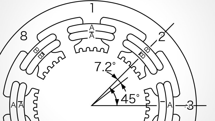
To understand how the motor moves, consider the example of a two-phase unipolar stepper motor with a 1.8° step angle. The stator has eight magnetic poles arranged in 45° intervals, each of which has five teeth arranged at 7.2° intervals. Each magnetic pole also has a coil winding as shown in Figure 1. Passing a current through the coil as indicated in Table 1 generates a rotating magnetic field to the stator like that in Figure 2.
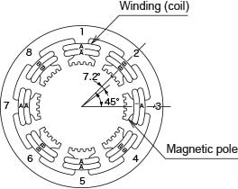 Figure 1 Stator
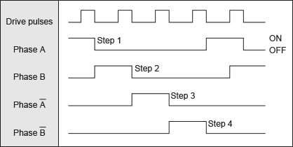 Table 1 Excitation sequence (single-phase excitation)
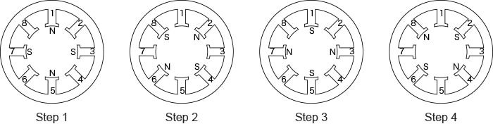 Figure 2 Rotating magnetic field generated by alternating excitation phase
The rotor is made up of a magnet and two rotor cores with 50 teeth. The rotor cores are offset from one another by one half of the pitch. Figure 3 shows how the rotor moves when the rotor excitation phase is alternated.
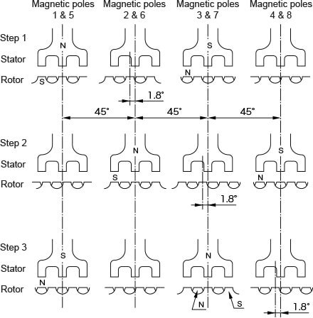 Figure 3 Single-phase excitation drive
- Step 1
- Excitation of phase A causes the S pole teeth of the rotor core to align with magnetic poles 1 and 5 of the stator and the N pole teeth to align with magnetic poles 3 and 7, such that both S and N are held steady by magnetic attraction. In this case, the S pole teeth of the rotor core are phase-lagged relative to magnetic poles 2 and 6 of the stator, and the N poles are phase-lagged relative to magnetic poles 4 and 8, in both cases by one-quarter pitch (1.8°).
- Step 2
- Next, phase B is excited instead. As the point of stability for this excitation is where the teeth of stator magnetic poles 2 and 6 and magnetic poles 4 and 8 are aligned with rotor teeth, excitation of phase B causes the rotor to rotate by one-quarter pitch (1.8°).
- Step 3
- Each subsequent alternation of the excitation also causes the rotor to rotate by one-quarter pitch.
How stepper motors are controlled
The rotation of a stepper motor is controlled precisely by applying electric signals. The signals are pulses generated by turning electricity on and off, and the angle of rotation is determined by the number of pulses input to the driver. Likewise, the speed of the motor is proportional to the pulse rate.
The angle, speed, and direction of rotation can be controlled using any of the following three pulse input patterns.
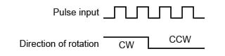
Single pulse mode
In this mode, pulses are input to drive rotation and the direction signal is held high or low to specify the direction of rotation.
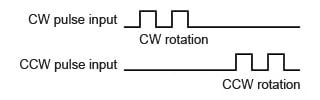
Double pulse mode
In this mode, separate clockwise (CW) and counter-clockwise (CCW) pulse inputs determine the direction of rotation. That is, CW pulses turn the motor clockwise and CCW pulses turn it counter-clockwise.
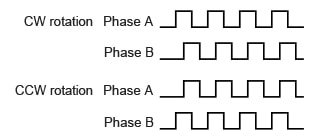
Phase A/phase B pulse mode
In this mode, separate phase A and phase B pulses are input with a phase offset of about 90° and the generated direction of rotation is determined by whether this phase difference is leading or lagging. That is, the motor turns clockwise if phase A is leading and counter-clockwise if phase B is leading.
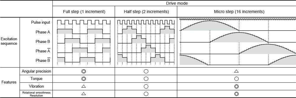
Changes to the excitation sequence can also further vary the motor characteristics to suit different applications, driving it in full steps, half steps, or micro steps. Micro-step drive provides more precise control over step angle, by supplying an excitation current that varies from a smooth sine wave by only very small gradations.
A typical stepper motor generates damped oscillations due to halting after each step. This can be a source of vibration and noise. The use of micro-step drive can potentially reduce this low-speed vibration and noise by making the step angle smaller, thereby minimizing this damped oscillation. Although micro-step drive tends to reduce angular precision slightly compared to other drive modes, it is a very useful option when the requirement is for low vibration and noise.
Stepper motors operated by simple mechanism
Stepper motors are motors that rotate in fixed angular increments. With a simple design made up of a magnet and coils, their high precision and low rate of faults make them an attractive proposition. They are easy to control using electric pulses, with their angle and speed of rotation being determined by the number and rate of pulses input and the pulse input mode. We hope you will be able to put these motors to good use based on a thorough understanding of how they are controlled.
Overcoming your problems with stepper motors
ASPINA supplies not only standalone stepper motors, but also system products that incorporate drive and control systems as well as mechanical design. These are backed by comprehensive support that extends from prototyping to commercial production and after-sales service.
ASPINA can offer solutions that are tailored to suit the functions and performance demanded by a diverse range of industries, applications, and customer products, as well as your particular production arrangements.
ASPINA supports not only customers who already know their requirements or specifications, but also those who are facing problems at early stages of development.
Do you struggle with the following concerns?
Motor selection
- Don't have detailed specifications or design drawings yet, but need advice on motors?
- Don't have anyone in-house with expertise in motors and can't identify what sort of motor will work best for your new product?
Motor and associated component development
- Want to focus your resources on core technology, and outsource drive systems and motor development?
- Want to save the time and effort of redesigning existing mechanical components when replacing your motor?
Unique requirement
- Need a custom motor for your product, but been declined from your usual vendor?
- Can't find a motor that gives you the control you require, and about to give up hope?
Seeking answers to these problems? Contact ASPINA, we're here to help.
List of the same series columns
- NEMA17 stepper motor selection guide: Mounting dimensions, applications, selection and problem solving
- NEMA stepper motor sizes chart and selection guide
- What does a stepper motor do?
- What is a brushless DC motor? What is the difference between brushless motor and brushed motor?
- What is a DC motor? - DC motor types, how they work, and how to control them
- Applications for blower motor
- What is a blower motor?
- Features and applications of DC motors
- Advantages of brushless DC motors over brushed DC motors
- Is this brushless motor cheap or expensive? - What factors determine its price?
- What is a geared brushless DC motor?
- How does an electronic speed controller for a brushless DC motor work? And what should you consider when you choose the right one?
- Small brushless motors
- What are the disadvantages of brushless DC motors? And how can they be overcome?
- Advantages of brushless DC motors: How they differ from brushed DC motors
- What is an actuator?
- Do brushless DC motors require a drive circuit? – Controlling brushless DC motors
- What is a stepper motor?
- What is an electric motor?
- How are stepper motors controlled? - Speed control of stepper motors
- How are DC motors controlled? - Speed control of DC motors
- Brushless DC motor applications: examples that demonstrate their features
- Stepper motor applications: Examples that demonstrate their features
- What are the differences between brushed and brushless DC motors?
- What is a PSC motor
- What is a servo motor?
- What is a blower?
Related information
-
NEMA17 stepper motor selection guide: Mounting dimensions, applications, selection and problem solving
-
IEC 60601-1 Explained: Key motor selection considerations for medical devices
-
ASPINA’s new servo motors enhance competitiveness in medical device development
-
NEMA stepper motor sizes chart and selection guide
Contact us for more information
- New inquiry
- Prototype
- Upgrade
- Customization
- Your spec
- Literature
- Support
- Others